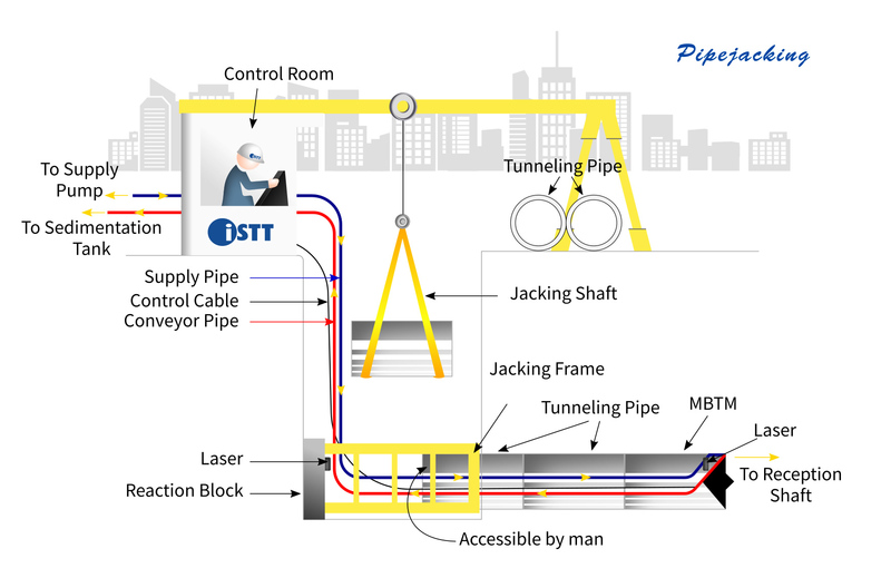
Pipe jacking is a tunneling method where a pipe being installed is used also as ground support during the tunneling operation. In this method, sections of pipe are lowered into the launching shaft and are thrust forward using jacks at the launching shaft as the tunnel advances. At the excavation face, a variety of equipment and configurations may be used according to the ground and groundwater conditions. In good ground conditions, a steel cylinder pushed ahead of the pipe sections provides immediate ground protection and the face may remain stable enough for hand or machine excavation without any special measure for face support. In more difficult ground conditions, partial face support or a closed excavation system using slurry for face support or an earth-pressure-balance (EPB) system may be required.
The key difference from conventional tunneling is that the lateral ground support for the tunnel is provided by the pipes jacked from the launching shaft rather than the tunnel ground support being installed just behind the tunnel face. In pipe jacking, as the pipes are slid further and further through the ground, the frictional forces on the pipes lead to an increase in jacking loads that must be applied. This provides limitations on the length of individual pipe jacking installations that are not present in conventional tunneling. Nevertheless, long installations with pipe jacking are possible with the right preparations and equipment – with the longest single installation made to date being 2.5 km for a 3 m internal diameter pipe in Germany.

Microtunneling is a form of pipe jacking installation. It is defined as a remotely-controlled, guided, pipe-jacking operation that provides continuous support to the excavation face by applying mechanical or fluid pressure to balance groundwater and earth pressures. Support at the excavation face is a key feature of microtunneling, distinguishing it from traditional open-shield pipe-jacking. Microtunneling is used to install pipelines beneath highways, railroads, runways, harbors, rivers, and environmentally sensitive areas.
Originally, the term microtunneling was used to describe tunneling for tunnel diameters for which a person was not allowed to enter the tunnel (typically less than 0.9 m or 1.0 m). The term is now used also to describe the method (i.e. not requiring a person to enter) rather than a specific diameter range. Regional differences remain in the usage of the terminology.
The following detailed description is based on a slurry-type machine.
Microtunneling requires jacking and reception shafts at the opposite ends of each drive. The microtunneling process is a cyclic pipe jacking operation. A microtunnel boring machine (MTBM) is pushed into the earth by hydraulic jacks mounted and aligned in the jacking shaft. The jacks are then retracted and the slurry lines and control cables are disconnected. A product pipe or casing is lowered into the shaft and inserted between the jacking frame and the MTBM or previously jacked pipe. Slurry lines and power and control cable connections are made, and the pipe and MTBM are advanced another drive stroke. This process is repeated until the MTBM reaches the reception shaft. Upon drive completion, the MTBM and trailing equipment are retrieved and all equipment removed from the pipeline. Most microtunneling operations include a hydraulic jacking system to advance the MTBM and pipe string, a closed loop slurry system to transport the excavated spoils, a slurry cleaning system to remove the spoil from the slurry water, a lubrication system to lubricate the exterior of the pipe string during installation, a guidance system to provide line and grade control, an electrical supply and distribution system to power equipment, a crane to hoist pipe sections into the jacking shaft, and various trucks and loaders to transport spoil off site. MTBMs have a rotating cutting head to excavate the ground material, a crushing cone to crush larger particles into smaller sizes for transport through the slurry lines, a hydraulic or electric motor to turn the cutting head, a pressurized slurry mixing chamber behind the cutter head to maintain face stability, an articulated steering unit with steering jacks for steering corrections, various control valves, pressure gauges, flow meters, and a data acquisition system. Additionally, the MTBM has in-line cameras to relay information to the operator and a target system for guidance control.
Different ground control and muck transport systems may be used depending on the ground conditions, machine diameter, etc. Auger-based microtunneling systems have been used and earth-pressure-balance systems can be substituted for slurry systems in larger diameter microtunneling projects.
Precise control of line and grade is accomplished using the guidance system and steering jacks to locate and steer the MTBM during a microtunneling drive. The guidance system usually consists of a reference laser mounted in the jacking shaft, which transmits a beam onto a target mounted inside the articulated section of the MTBM. For curved microtunnel projects, gyroscopic survey systems combined with water level sensor systems (for vertical alignment) may be used. These data and other operational information are transmitted through wire cables to a control cabin located on the surface. Microtunneling machines are capable of independently counter-balancing earth and hydrostatic pressures. Earth pressure is counter-balanced by careful control of advance rates and excavation rates of spoil materials. Groundwater pressure is counter-balanced by using pressurized slurry in the soil-mixing chamber of the MTBM.
Pipe Jacking![]() Descargar / Download
Descargar / Download


